Precision Gear Racks for Custom Machinery
Special machinery often needs the accuracy discipline of a catalogue precision rack while keeping drawing-specific holes, ends, section geometry or inspection datums. This is where standard tooth systems and custom machining frequently meet.
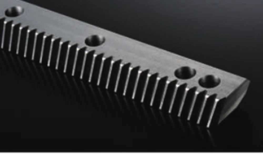
What the rack drive has to do
The right question is not whether the part is “standard” or “custom.” The useful distinction is which features are fixed by a tooth system and which features belong to the machine design. Keeping those two groups clear makes quotation, production and inspection easier.
The application should be described as a complete axis. That means the rack tooth system, pinion, gearbox interface, mounting base and lubrication method are reviewed together instead of assuming the rack alone determines performance.
Define the machine duty before fixing the component
These inputs make the difference between a quotation based on geometry alone and one that reflects how the drive will actually be used.
| Functional datums | Which surfaces locate the rack and which dimensions control the mesh. |
|---|---|
| Tooth data | Module/pitch, pressure angle, tooth form, helix angle and quality requirements. |
| Secondary machining | Hole pattern, counterbores, dowels, ends, shoulders or reliefs. |
| Material/process | Material grade, heat treatment, finish and coating if any. |
| Production plan | Prototype quantity, validation batch and repeat production demand. |
Products commonly evaluated for this application
The choices below are starting points, not automatic selections. Final suitability depends on the drawing and the operating data.
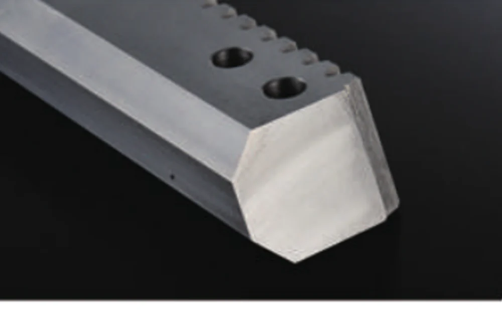
Kundenspezifisch gefertigte Zahnstange
For drawing-specific lengths, holes, ends and mounting features.
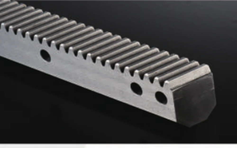
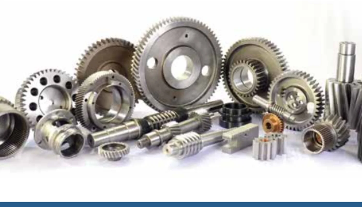
Custom Helical Gear
For companion gearing or custom mechanisms beyond the rack itself.
Installation details can erase or preserve the value of a precision rack
Make the drawing datum scheme match the way the part will be mounted and inspected. That reduces arguments about dimensions that are technically correct but referenced from the wrong surface.
If the rack joins another section, identify the required end relationship and how the joint will be set during machine assembly.
When a prototype is used to validate the design, record any approved changes before the production batch so the revision history stays controlled.
Information to send with the application enquiry
Send the current drawing revision, 3D model when useful, controlled datums/tolerances, tooth data, material and heat treatment, prototype quantity and expected repeat quantity. Note which dimensions are function-critical and which can be adjusted for manufacturability.
If some values are still open, mark them as design targets. That is more useful than inserting a guessed specification that later becomes difficult to change.
Senden Sie die Details, die das Teil definieren.
Ein aussagekräftiges Angebot beginnt mit der Geometrie und dem Betriebskontext. Senden Sie die Zeichnung, die Stückzahl und die Anforderungen an die Regelung; bei zahnstangengetriebenen Achsen fügen Sie bitte, falls vorhanden, Informationen zu Verfahrweg, Geschwindigkeit, Beschleunigung, Last und dem zugehörigen Ritzel oder Getriebe hinzu.
Bestellung: Die Mindestbestellmenge (MOQ) ist je nach Produkttyp und Bestellwert flexibel. Geeignete Muster für Neukunden umfassen 1–5 Stück; Bestellungen mit gemischten Modellen werden ab einem Gesamtwert von ca. 1.500 USD unterstützt, während Bestellungen von 1–2 Stück zu einem höheren Stückpreis möglich sind.
Timing & terms: Standardteile werden üblicherweise innerhalb von 10-25 Werktagen geliefert, kundenspezifische Komponenten innerhalb von 20-45 Werktagen und Projektausrüstung innerhalb von 45-120 Werktagen. EXW, FOB, CIF und DAP sind gängige Lieferbedingungen; FCA, CFR, CPT, CIP und DDP können im Einzelfall besprochen werden.