Precision Gear Racks for Custom Machinery
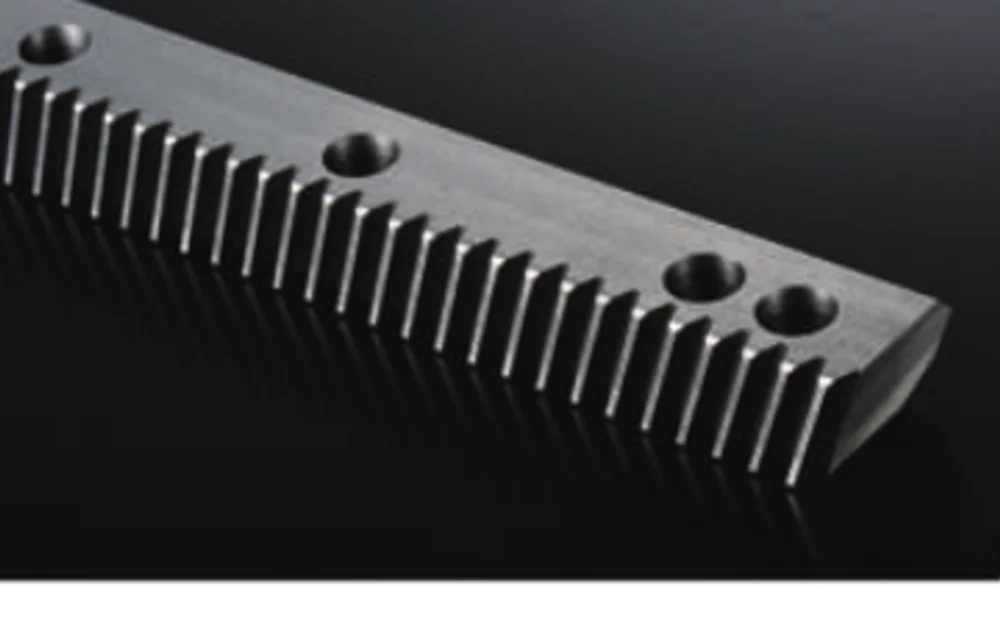
Special machinery often needs the accuracy discipline of a catalogue precision rack while keeping drawing-specific holes, ends, section geometry or inspection datums. This is where standard tooth systems and custom machining frequently meet.
What the rack drive has to do
The right question is not whether the part is “standard” or “custom.” The useful distinction is which features are fixed by a tooth system and which features belong to the machine design. Keeping those two groups clear makes quotation, production and inspection easier.
The application should be described as a complete axis. That means the rack tooth system, pinion, gearbox interface, mounting base and lubrication method are reviewed together instead of assuming the rack alone determines performance.
Define the machine duty before fixing the component
These inputs make the difference between a quotation based on geometry alone and one that reflects how the drive will actually be used.
| Functional datums | Which surfaces locate the rack and which dimensions control the mesh. |
|---|---|
| Tooth data | Module/pitch, pressure angle, tooth form, helix angle and quality requirements. |
| Secondary machining | Hole pattern, counterbores, dowels, ends, shoulders or reliefs. |
| Material/process | Material grade, heat treatment, finish and coating if any. |
| Production plan | Prototype quantity, validation batch and repeat production demand. |
Products commonly evaluated for this application
The choices below are starting points, not automatic selections. Final suitability depends on the drawing and the operating data.
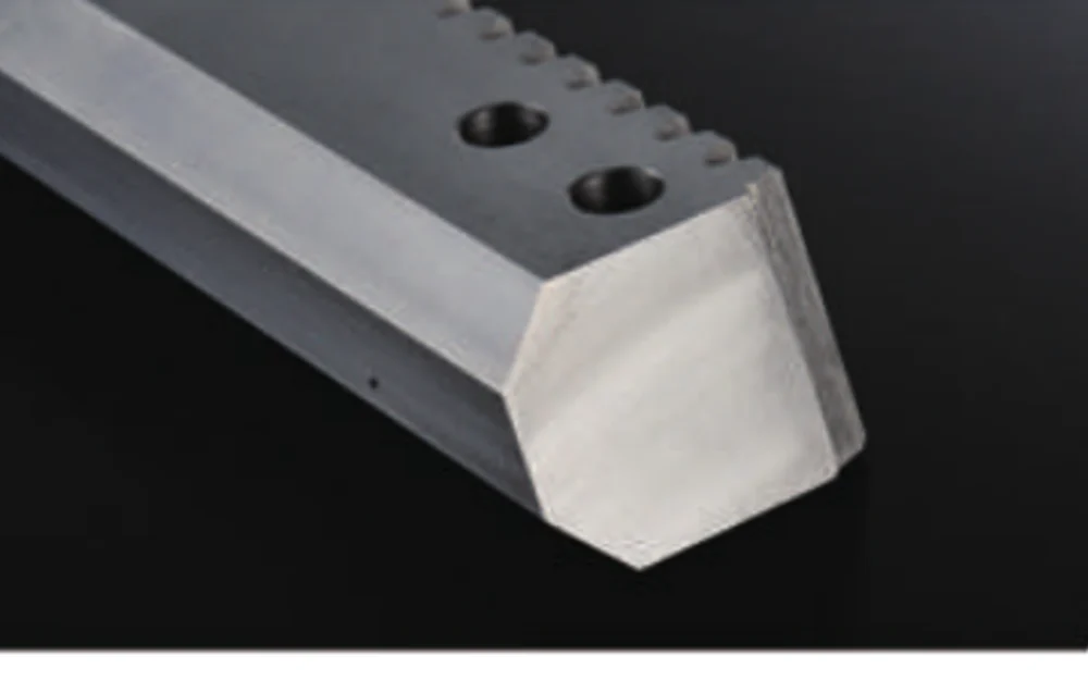
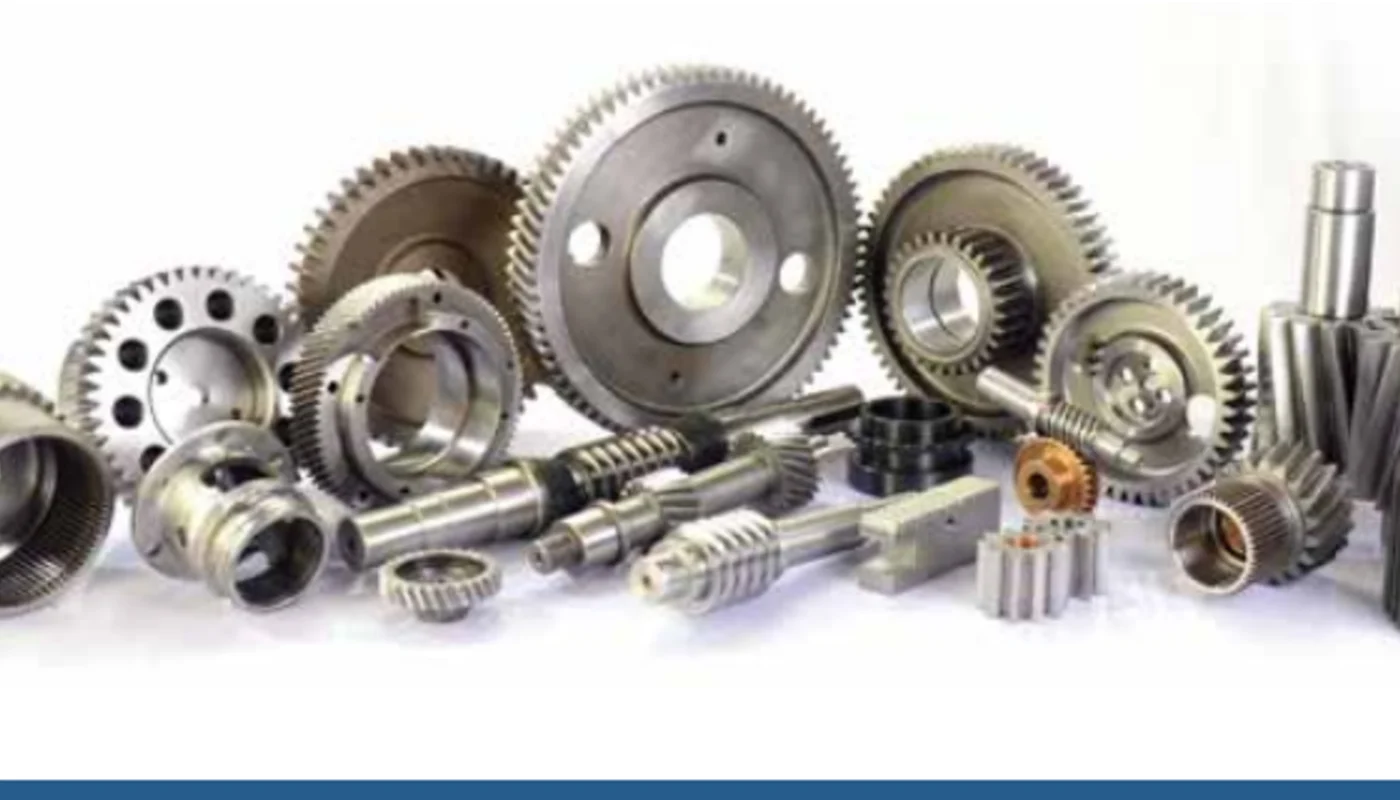
Custom Machined Gear Rack
For drawing-specific lengths, holes, ends and mounting features.
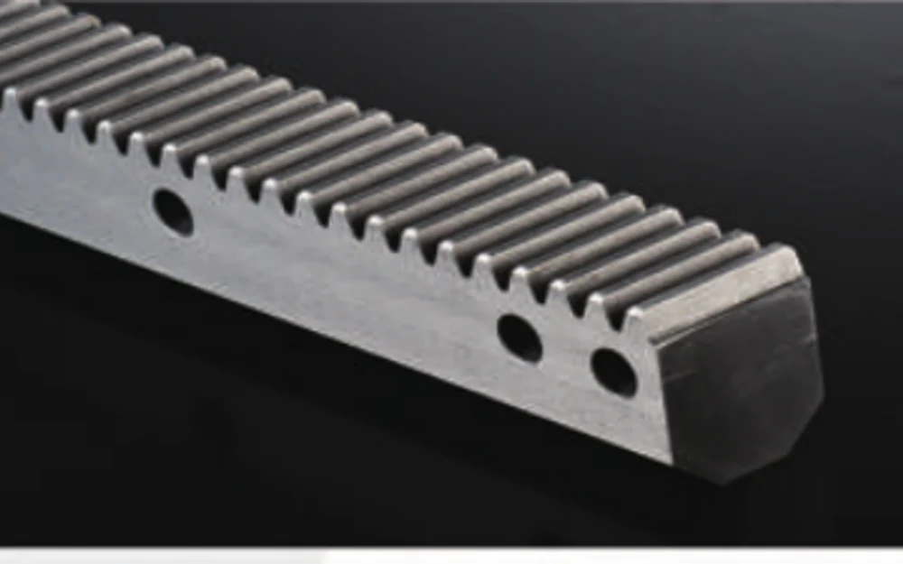
Installation details can erase or preserve the value of a precision rack
Make the drawing datum scheme match the way the part will be mounted and inspected. That reduces arguments about dimensions that are technically correct but referenced from the wrong surface.
If the rack joins another section, identify the required end relationship and how the joint will be set during machine assembly.
When a prototype is used to validate the design, record any approved changes before the production batch so the revision history stays controlled.
Information to send with the application enquiry
Send the current drawing revision, 3D model when useful, controlled datums/tolerances, tooth data, material and heat treatment, prototype quantity and expected repeat quantity. Note which dimensions are function-critical and which can be adjusted for manufacturability.
If some values are still open, mark them as design targets. That is more useful than inserting a guessed specification that later becomes difficult to change.
部品を定義する詳細情報を送信してください。
有用な見積もりを作成するには、まず形状と動作環境を把握することが重要です。図面、数量、制御要件をお送りください。ラック駆動軸の場合は、移動量、速度、加速度、負荷、および対応するピニオンまたはギアボックスの情報(入手可能な場合)も併せてお送りください。
注文方法: 最小注文数量(MOQ)は、製品の種類と注文金額によって柔軟に対応可能です。新規顧客向けのサンプルは1~5個が適切です。複数モデルを組み合わせた注文は、合計金額が1,500米ドル以上であれば対応可能ですが、1~2個の場合は単価が高くなります。
時期と条件: 標準部品の納期は通常10~25営業日、特注部品は20~45営業日、プロジェクト機器は45~120営業日です。EXW、FOB、CIF、DAPは一般的に利用可能ですが、FCA、CFR、CPT、CIP、DDPについては個別にご相談ください。