説明
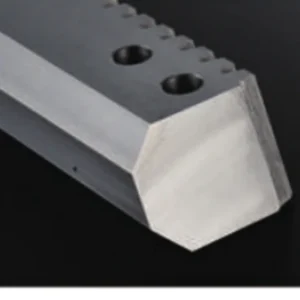
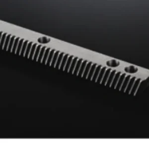
Linear Guide Gear Rack
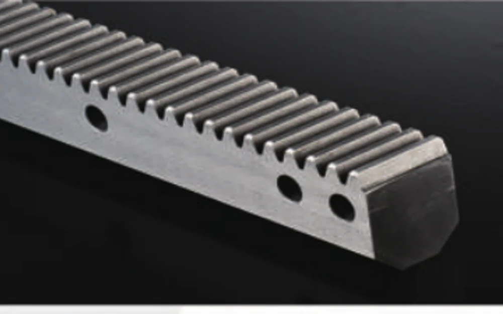
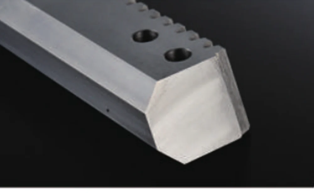
Rack profiles with guide-style sections and mounting features for integrated linear assemblies and custom machine structures.

Where this component fits
Rack profiles with guide-style or integrated mounting geometry for machine structures that combine linear support and rack-drive packaging.
Custom automation, transfer systems, compact machine axes and integrated linear assemblies are typical uses.
Technical specifications
The values below are the current catalogue and drawing-based scope already associated with this product family. Where a value is described as project-specific or “confirm drawing,” the released drawing remains the final technical reference.
| Profile | Guide/rail-style rack section |
|---|---|
| Mounting | Through/counterbored holes or custom patterns |
| 歯の形 | Straight or helical by drawing |
| Length | Standard sections or cut/custom lengths |
| 材料 | Per load, wear and drawing requirement |
Selection should follow the mating component and the real duty
The profile and mounting datums are central to this type of part. Tooth geometry may be familiar, but section shape, guide relationship and hole pattern can make the component fully drawing-specific.
If a requested parameter is not yet fixed, provide the functional target and allow it to remain an open selection item. That is safer than locking the project to an assumed value that has not been checked against the mating component or machine.
Details that change the quotation
These fields help separate a standardizable configuration from a part that needs drawing-specific machining or inspection.
| Tooth system | Confirm module/DP/CP, pressure angle, tooth form and helix details where relevant. |
|---|---|
| Machine duty | For driven axes provide travel, load, speed, acceleration, duty and positioning target. |
| Material/treatment | Use the drawing requirement or state the performance need if a material route is still open. |
| Mounting geometry | Length, cross-section, hole pattern, end conditions and datum surfaces. |
| Finish/accuracy | State the drawing tolerance or functional accuracy need; do not default to the highest grade. |
| Quantity | Prototype, first production batch and repeat demand if known. |
Process route follows the ordered specification
Rack manufacturing can combine blank preparation, datum machining, tooth generation, heat treatment where specified, tooth finishing where required, secondary hole/end machining and final inspection. The sequence depends on material, hardness, accuracy and distortion risk.
Material substitutions, heat-treatment changes and tolerance relaxations should be approved before production. For repeat orders, the approved drawing revision and any agreed inspection scope should remain attached to the order.
Fit, mounting and mating-part considerations
The machine designer should define which surfaces are functional datums and how the rack/guide geometry is referenced during assembly. That information should appear on the drawing.
For replacement work, send the existing part or assembly information as identification support, but confirm the production dimensions before release. Visual similarity is not a substitute for the tooth and interface data.
Inspection should follow the functional datums
Inspection should emphasize section dimensions, datum relationships, mounting features and tooth location relative to the integrated guide geometry.
If dimensional reports, material certificates or heat-treatment records are required with the order, identify them in the RFQ so they are included in the quality plan rather than requested after production is complete.
Products commonly reviewed together
Related components are shown as practical design companions, not as claims that every item is automatically compatible. Match the actual drawing and mating tooth data before ordering.
What to send for a useful quotation
Attach the latest drawing and state quantity, material, treatment, tooth data and critical inspection requirements. For rack-driven motion, add the axis duty and the mating pinion/gearbox details where available. STEP or DWG files help when secondary machining and interfaces are complex.
部品を定義する詳細情報を送信してください。
A useful quotation starts with the geometry and the operating context. Send the drawing, quantity and controlled requirements; for rack-driven axes, add travel, speed, acceleration, load and the mating pinion or gearbox information when available.
注文方法: 最小注文数量(MOQ)は、製品の種類と注文金額によって柔軟に対応可能です。新規顧客向けのサンプルは1~5個が適切です。複数モデルを組み合わせた注文は、合計金額が1,500米ドル以上であれば対応可能ですが、1~2個の場合は単価が高くなります。
Timing & terms: 標準部品の納期は通常10~25営業日、特注部品は20~45営業日、プロジェクト機器は45~120営業日です。EXW、FOB、CIF、DAPは一般的に利用可能ですが、FCA、CFR、CPT、CIP、DDPについては個別にご相談ください。