Description
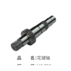
Splined Bore Sun Gear
Sun gears with internal splines or other torque-transmitting bore interfaces for motor, shaft or carrier-side integration.
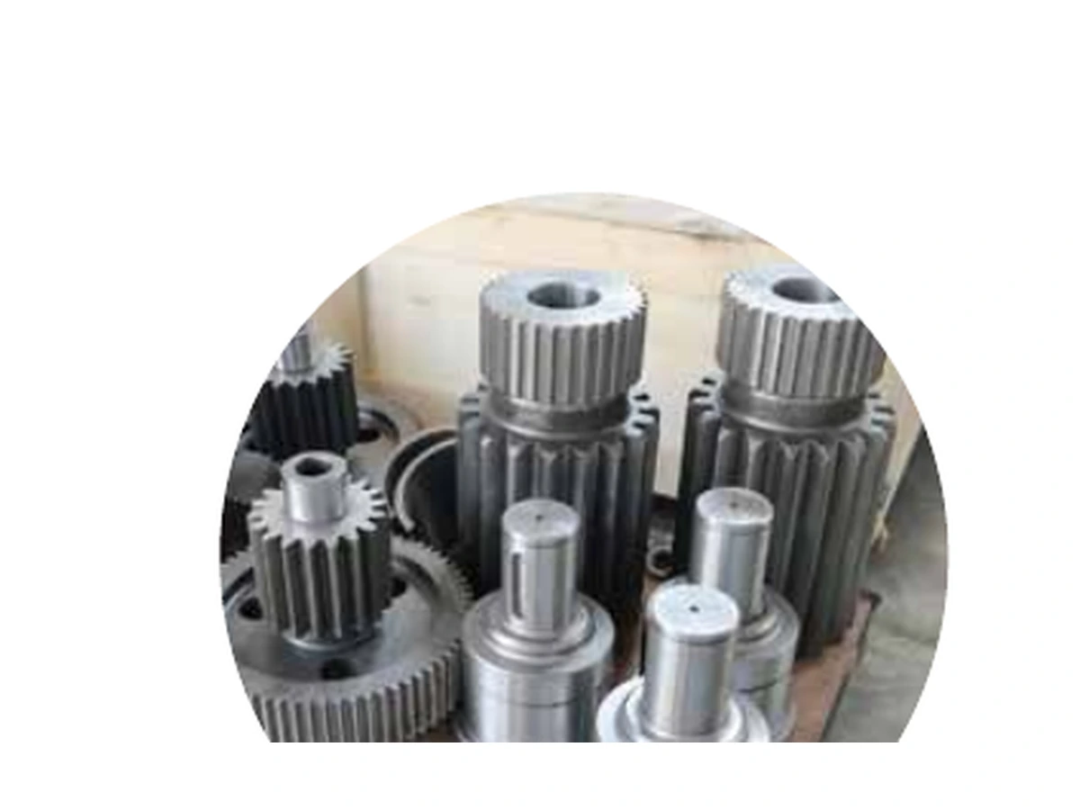
Specify the sun gear as part of a planetary mesh
The spline is part of the torque path and must be treated as an engineered interface, not as a secondary bore feature. Specify spline system, tooth count, module/DP or pitch, pressure angle, fit/tolerance class, effective length and the axial locating method. Concentricity between spline and gear teeth is especially important when the spline is the rotating datum.
For quotation, the most reliable input is the released drawing plus mating-gear data. If the design is still open, provide the required ratio, torque, speed, duty cycle, package envelope and interface constraints so the unresolved items can be identified before manufacturing.
Information used to define the ordered part
Sun gears are not interchangeable simply because two parts have a similar diameter. The tooth system and the rotating interface must match the planetary stage.
| Component | Spur or helical sun gear with internal spline |
|---|---|
| Primary interface | Involute spline, straight-sided spline or drawing-specific internal form |
| Tooth system | Metric module or diametral pitch (DP) as defined by drawing |
| Pressure angle | Drawing-controlled; do not assume from outside diameter alone |
| Tooth count | Required for quotation and mesh verification |
| Gear quality | ISO, DIN, AGMA, JIS or customer-specific requirement can be reviewed as stated on the drawing |
| Materials | Alloy and carbon gear steels selected to drawing; examples used in industrial gear work include 20CrMo, 16MnCr5, 18CrNiMo7-6, 8620-type and 42CrMo families |
| Heat treatment | Carburizing, nitriding, induction hardening, through-hardening or Q&T where appropriate to the design |
| Inspection | Tooth geometry, runout, bore/spline/journals and drawing datums as applicable |
| Supply basis | New design, drawing-to-print, sample-supported replacement or matched planetary set |
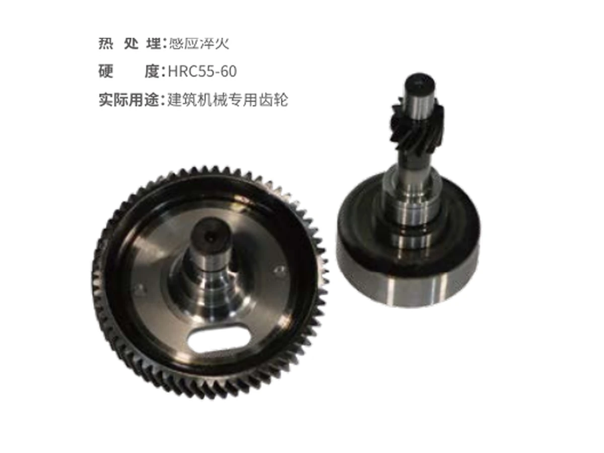
Check sun, planet and ring data together
A conventional planetary stage combines a central sun gear, one or more planet gears, an internal ring gear and a carrier. The tooth counts and mesh geometry constrain each other. For a replacement, measuring only the damaged sun gear can miss profile shift, backlash strategy or mating-gear wear.
When available, send the planet gear and ring gear drawings, gearbox assembly drawing, original tooth counts, center-distance information and any contact-pattern or backlash requirement. This is especially important for helical planetary stages.
Process planning follows geometry, material and required quality
Depending on geometry and volume, internal splines may be shaped, broached, skived or otherwise machined. The heat-treatment route must account for both tooth and spline requirements, followed by inspection with the gauges or measured characteristics called out on the drawing.
The manufacturing route can therefore differ even between two sun gears of the same module. Batch quantity also matters because it affects tooling, fixturing and which spline or internal-feature process is economical.
What to send for an accurate quotation
Send the drawing or a clear set of gear data, then add the operating information that is not visible on the drawing. A sample can support a replacement project, but it should not be used to guess an unknown heat treatment or quality grade.
| Geometry | Module/DP, tooth count, pressure angle, spur/helical form, helix angle and hand where applicable |
|---|---|
| Interface | Bore, keyway, spline, shaft, journal, thread and locating faces |
| Material / heat treatment | Material grade, hardness or case requirement, surface treatment if specified |
| Quality / inspection | Gear-quality standard and grade, runout, profile/lead or special inspection requirements |
| Duty | Torque, speed, duty cycle, reversals, lubrication and working temperature when relevant |
| Mating data | Planet/ring tooth counts or drawings, carrier/center-distance information |
| Commercial | Quantity, target delivery, packaging and Incoterm |