Planetary Gearboxes Sun Gear Applications
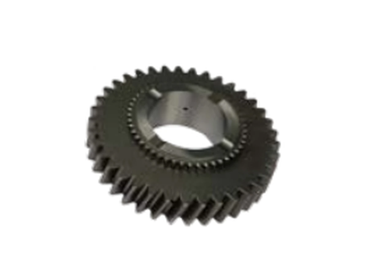
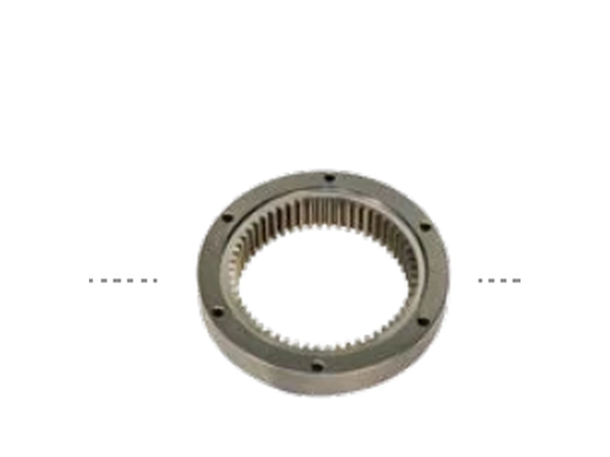
Planetary reducers use the sun gear as one of the three primary gear members, with planet gears orbiting between the sun and internal ring.
What the Sun Gear has to do in this application
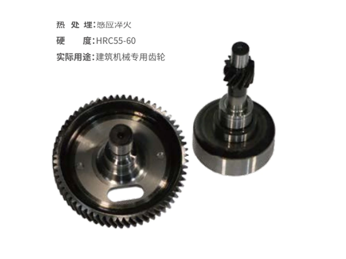
Reducer designers usually care about torque density, ratio, backlash, life and bearing/support arrangement. A replacement buyer additionally needs to preserve the original tooth geometry and shaft interface.
The central gear must remain compatible with the planet gears and ring gear while also locating correctly on its shaft, spline or integrated journal system. That combination is why a complete drawing is preferred to a simple dimensional sketch.
Data that should accompany the drawing
| Application data | Nominal and peak torque, input speed, stage ratio, planet count, lubrication, duty cycle and the sun/planet/ring tooth counts. |
|---|---|
| Tooth definition | Module/DP, tooth count, pressure angle, spur/helical form and any profile modification |
| Helical data | Helix angle and hand for helical stages |
| Interfaces | Bore/spline/shaft, bearing or journal datums and axial locating faces |
| Material / treatment | Keep the approved material and heat-treatment callout; proposed changes require engineering review |
| Mating components | Planet and ring gear tooth counts/drawings, planet count and carrier relationship |
Where a replacement project can go wrong
A sun gear that looks dimensionally similar can still fail to mesh correctly if pressure angle, profile shift, helix data or the spline datum differs.
Also check how the component is retained axially, how torque reaches the sun gear, and whether lubrication reaches the mesh and spline/journal interface. When the original part failed, include photographs and failure location so the new RFQ does not simply copy a damaged geometry without context.
Review the complete planetary stage when useful