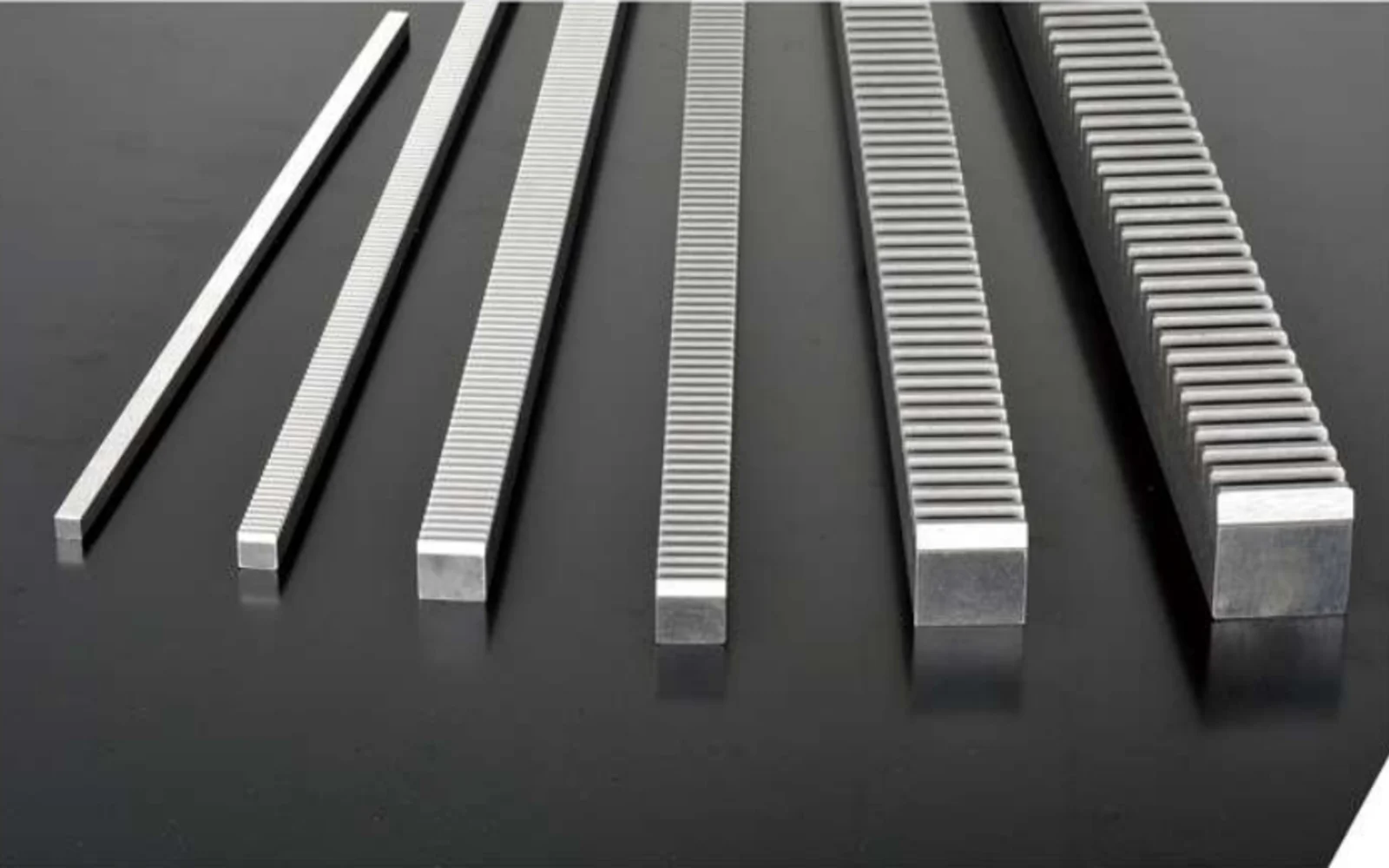
A gear rack for a long machine axis should be selected from the motion requirement first, then from tooth size and manufacturing route. Travel, moved mass, acceleration, speed, duty and positioning requirements determine how demanding the rack-and-pinion set really is.
Start with the axis, not with module
Record whether the motion is horizontal or vertical, the total stroke, supported mass, external process force, maximum speed, acceleration and how often the axis reverses. On a long axis, also note how many rack sections will be joined and where the pinion sits relative to the guideways.
These values do not directly create a rack drawing, but they establish the duty. A rack chosen only because it has the same module as an old component can still be wrong for the desired speed, wear life, backlash or mounting arrangement.
Define the tooth system and the mating pinion together
| Module / pitch | Must match the pinion and should be checked against the force level and available tooth size. |
|---|---|
| Pressure angle | Use the released drawing or system standard; 20 degrees is a common industrial reference but should not be assumed blindly. |
| Tooth form | Straight teeth simplify geometry; helical teeth can provide more gradual engagement but introduce an axial force component. |
| Pinion tooth count | Influences pitch diameter, linear travel per revolution and the gearbox/motor operating point. |
| Backlash setting | Depends on rack tooth thickness, pinion geometry, gearbox behaviour and the mechanical adjustment method. |
Choose the finishing route from the positioning requirement
Grinding is useful when the axis needs a tighter tooth finish or pitch control than a basic milled rack is intended to provide. It is not automatically necessary on every CNC or cutting axis. A hardened milled rack can be entirely appropriate on robust machinery where the control system and process do not demand a ground-tooth level of motion quality.
Ask what the machine actually needs: high rapid speed, repeatable positioning, low running noise, frequent reversal, long service life or simply a reliable way to move a heavy carriage. The answer points toward the right manufacturing route.
Long axes add an installation problem
A multi-section rack is only as good as the transition between adjacent sections. The mounting base, stop/datum surface and joining method should keep pitch continuity across the joint. A local step at the joint can be felt by the pinion every time it passes.
The guideway and rack datum also need to remain related over the full travel. If the rack moves closer to or farther from the pinion along the axis, backlash and contact change even when every rack section was manufactured correctly.

Do not leave lubrication until commissioning
Lubrication method, protection from chips/coolant and service access should be part of the machine layout. A precision rack operating dry or full of abrasive debris will not preserve its intended surface condition. The lubrication system should reach the active travel and be inspectable without dismantling major machine structures.
Prepare an RFQ that an application engineer can use
Send the rack drawing if it already exists. If the design is open, send the axis layout and the motion data, then identify which values are fixed and which can be selected. Include the proposed motor/gearbox and pinion data when available, plus quantity, material preferences and the accuracy or inspection requirement that matters to the machine.
해당 부품을 정의하는 세부 정보를 보내주세요.
정확한 견적을 위해서는 먼저 장치의 형상과 작동 환경을 명확히 제시해야 합니다. 도면, 수량, 그리고 요구되는 사양을 보내주십시오. 랙 구동 방식의 경우, 이동 거리, 속도, 가속도, 하중, 그리고 가능하다면 연결 피니언 또는 기어박스 정보도 함께 보내주시기 바랍니다.
주문하기: 최소 주문 수량(MOQ)은 제품 유형 및 주문 금액에 따라 유연하게 조정 가능합니다. 신규 고객 샘플은 1~5개부터 주문 가능하며, 여러 모델을 혼합 주문하는 경우 총 주문 금액이 미화 1,500달러 이상이면 지원됩니다. 1~2개 주문 시에는 단가가 더 높게 책정될 수 있습니다.
시기 및 조건: 표준 부품은 일반적으로 10~25영업일, 맞춤형 부품은 20~45영업일, 프로젝트 장비는 45~120일이 소요됩니다. EXW, FOB, CIF 및 DAP 조건이 일반적으로 제공되며, FCA, CFR, CPT, CIP 및 DDP 조건은 개별 사례에 따라 협의 가능합니다.