Gear Racks for CNC Machine Tools
For long CNC feed axes, the rack and pinion have to carry the commanded feed force while preserving predictable positioning over the whole travel. Rack joints, mounting datums and drive stiffness matter as much as the nominal module.
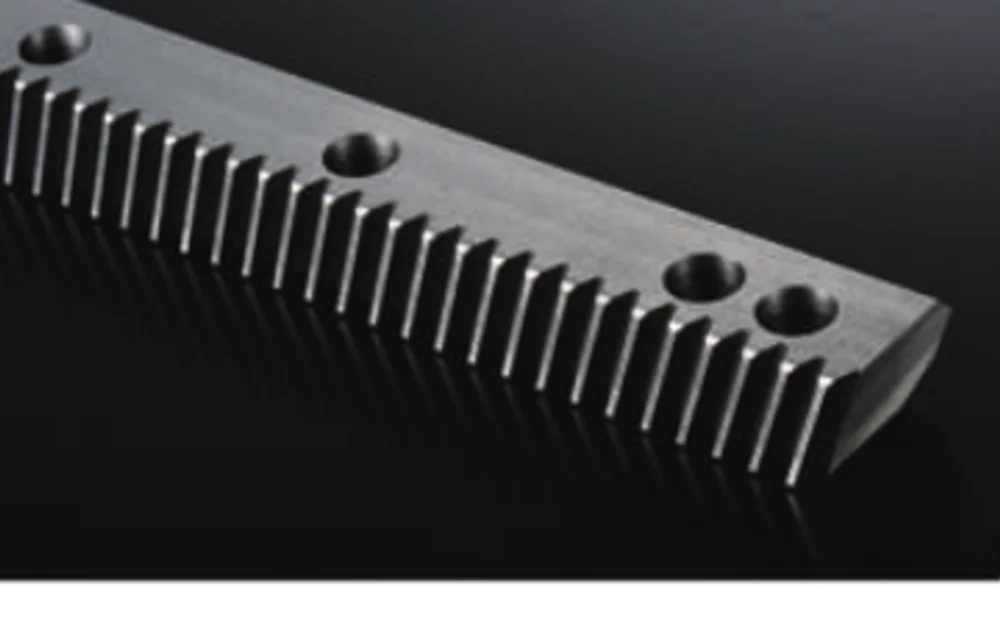
What the rack drive has to do
CNC axes usually combine long travel with frequent direction changes and a demand for consistent motion. Ground racks are commonly evaluated when pitch consistency and smooth engagement are important, while hardened or milled racks can be suitable where the machine accuracy target is less demanding.
The application should be described as a complete axis. That means the rack tooth system, pinion, gearbox interface, mounting base and lubrication method are reviewed together instead of assuming the rack alone determines performance.
Define the machine duty before fixing the component
These inputs make the difference between a quotation based on geometry alone and one that reflects how the drive will actually be used.
| Axis geometry | Travel length, rack section length, horizontal/vertical orientation and the machine-base datum. |
|---|---|
| Moving load | Slide, spindle/head, tooling and process-force contribution. |
| Feed performance | Rapid-traverse speed, cutting-feed speed, acceleration and reversal frequency. |
| Positioning | Target positioning/repeatability, compensation strategy and allowable backlash. |
| Protection | Chip guards, coolant exposure, lubrication method and maintenance access. |
Products commonly evaluated for this application
The choices below are starting points, not automatic selections. Final suitability depends on the drawing and the operating data.
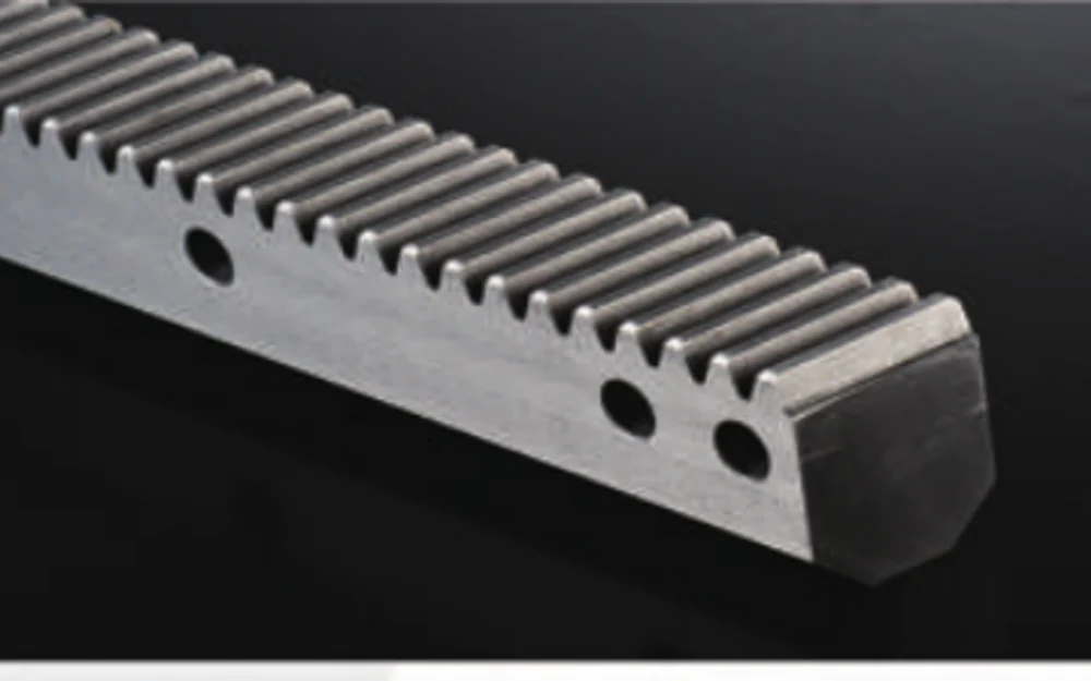
Ground Helical Gear Rack
A starting point for smooth high-quality long-travel axes where helical teeth suit the drive layout.
Installation details can erase or preserve the value of a precision rack
Machine-base straightness and the relationship between rack mounting face and guideway datum should be treated as part of the axis geometry.
Joined rack sections need a controlled pitch transition. The pinion should cross the joint without a local change in mesh or running feel.
Backlash is a system property. Rack tooth thickness, pinion geometry, gearbox torsional behaviour and mounting adjustment all contribute.
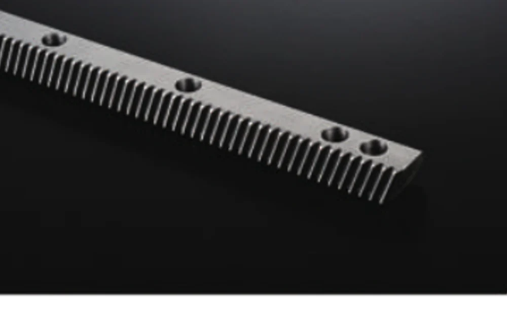
Information to send with the application enquiry
Send the axis layout, travel, load, feed speed, acceleration, required positioning/repeatability, proposed gearbox/pinion data and the rack mounting drawing. If the machine builder already has a compensation strategy, note how mechanical backlash is expected to be set.
If some values are still open, mark them as design targets. That is more useful than inserting a guessed specification that later becomes difficult to change.
Send the details that define the part.
A useful quotation starts with the geometry and the operating context. Send the drawing, quantity and controlled requirements; for rack-driven axes, add travel, speed, acceleration, load and the mating pinion or gearbox information when available.
Ordering: MOQ is flexible by product type and order value. Suitable new-customer samples can be 1-5 pcs; mixed-model orders are supported around USD 1,500+ combined, while 1-2 pcs can be considered at a higher unit price.
Timing & terms: Standard parts are typically 10-25 working days, custom components 20-45, and project equipment 45-120. EXW, FOB, CIF and DAP are commonly available; FCA, CFR, CPT, CIP and DDP can be discussed case by case.