Heavy Lifting & Long-Travel Rack Drives
Heavy positioning systems place a different emphasis on the tooth set: available feed force, shock load, structural stiffness, braking and serviceability can dominate over very fine positioning accuracy.

What the rack drive has to do
Larger tooth size, greater face width, stronger material routes and hardened teeth may be considered when the duty requires them, but the correct combination has to be checked against the actual load case. A nominal module by itself is not proof of capacity.
The application should be described as a complete axis. That means the rack tooth system, pinion, gearbox interface, mounting base and lubrication method are reviewed together instead of assuming the rack alone determines performance.
Define the machine duty before fixing the component
These inputs make the difference between a quotation based on geometry alone and one that reflects how the drive will actually be used.
| Load case | Moving mass, vertical load, external process force, shock and emergency-stop conditions. |
|---|---|
| Duty | Speed, acceleration, starts per hour and continuous/ intermittent operation. |
| Drive arrangement | Single or multiple pinions, gearbox ratio, brake and shaft/bearing support. |
| Structure | Rack support spacing, base stiffness and deflection under load. |
| Service | Lubrication access, inspection interval and replacement strategy. |
Products commonly evaluated for this application
The choices below are starting points, not automatic selections. Final suitability depends on the drawing and the operating data.
Induction-Hardened Gear Rack
Wear-resistant rack option for repeated industrial motion.
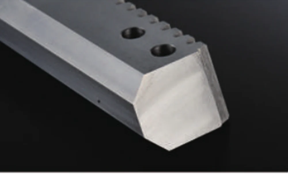
Custom Machined Gear Rack
For non-standard section sizes, holes, ends or structural interfaces.
Installation details can erase or preserve the value of a precision rack
Check the mounting structure for deflection under the worst load case. Misalignment caused by frame movement can reduce contact quality even when the rack itself is accurately made.
For lifting or vertical axes, the rack is only one part of the safety chain; braking, holding and control functions remain machine-level responsibilities.
Provide access for lubrication and tooth inspection, especially on equipment where the rack is partially enclosed after commissioning.
Information to send with the application enquiry
Send the maximum operating and peak/emergency loads, axis orientation, travel, speed, acceleration, duty, gearbox ratio, brake concept, pinion dimensions and structural mounting layout. If an existing drive is being replaced, include the previous part dimensions and the reason for replacement.
If some values are still open, mark them as design targets. That is more useful than inserting a guessed specification that later becomes difficult to change.
部品を定義する詳細情報を送信してください。
A useful quotation starts with the geometry and the operating context. Send the drawing, quantity and controlled requirements; for rack-driven axes, add travel, speed, acceleration, load and the mating pinion or gearbox information when available.
注文方法: 最小注文数量(MOQ)は、製品の種類と注文金額によって柔軟に対応可能です。新規顧客向けのサンプルは1~5個が適切です。複数モデルを組み合わせた注文は、合計金額が1,500米ドル以上であれば対応可能ですが、1~2個の場合は単価が高くなります。
時期と条件: 標準部品の納期は通常10~25営業日、特注部品は20~45営業日、プロジェクト機器は45~120営業日です。EXW、FOB、CIF、DAPは一般的に利用可能ですが、FCA、CFR、CPT、CIP、DDPについては個別にご相談ください。