Description
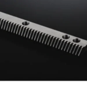
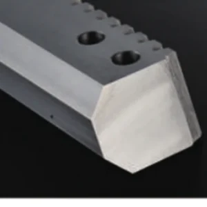
Ground Helical Gear Rack
Ground helical gear racks for applications where pitch accuracy, smooth engagement and repeatability matter more than a basic milled finish.
Where this component fits
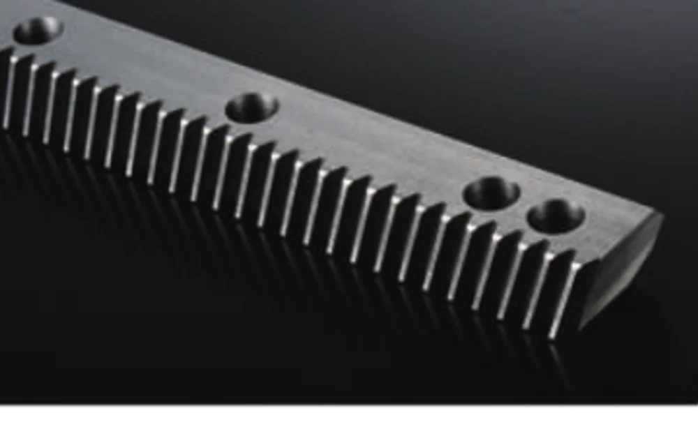
Ground helical racks for axes that need tighter tooth accuracy and smoother engagement than a basic milled finish is intended to provide.
Machine tools, high-speed cutting gantries, robot travel axes and precision automation are typical contexts where a ground helical rack may be evaluated.
Technical specifications
The values below are the current catalogue and drawing-based scope already associated with this product family. Where a value is described as project-specific or “confirm drawing,” the released drawing remains the final technical reference.
| Finish | Ground tooth flanks; other faces per drawing |
|---|---|
| Tooth form | Helical |
| Typical pressure angle | 20° for compatible series |
| Typical helix reference | 19°31′42″ for compatible series |
| Material / treatment | S45C/C45 or alloy-steel route depending on hardness and drawing |
Selection should follow the mating component and the real duty
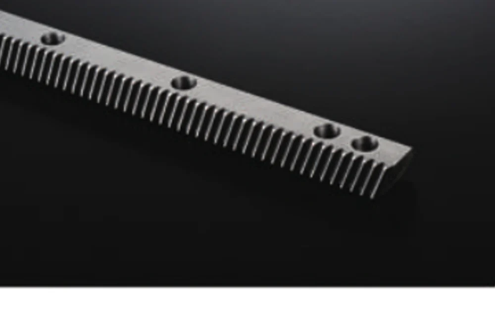
Grinding is a manufacturing route chosen for a defined accuracy or running requirement. It should be linked to the machine positioning, repeatability, reversal duty and noise/smoothness target rather than requested as a prestige feature.
If a requested parameter is not yet fixed, provide the functional target and allow it to remain an open selection item. That is safer than locking the project to an assumed value that has not been checked against the mating component or machine.
Details that change the quotation
These fields help separate a standardizable configuration from a part that needs drawing-specific machining or inspection.
| Tooth system | Confirm module/DP/CP, pressure angle, tooth form and helix details where relevant. |
|---|---|
| Machine duty | For driven axes provide travel, load, speed, acceleration, duty and positioning target. |
| Material/treatment | Use the drawing requirement or state the performance need if a material route is still open. |
| Mounting geometry | Length, cross-section, hole pattern, end conditions and datum surfaces. |
| Finish/accuracy | State the drawing tolerance or functional accuracy need; do not default to the highest grade. |
| Quantity | Prototype, first production batch and repeat demand if known. |
Process route follows the ordered specification
Rack manufacturing can combine blank preparation, datum machining, tooth generation, heat treatment where specified, tooth finishing where required, secondary hole/end machining and final inspection. The sequence depends on material, hardness, accuracy and distortion risk.
Material substitutions, heat-treatment changes and tolerance relaxations should be approved before production. For repeat orders, the approved drawing revision and any agreed inspection scope should remain attached to the order.
Fit, mounting and mating-part considerations
The benefit of a ground rack depends on the rest of the system. A flexible mounting base, poorly aligned pinion or inconsistent rack joint can dominate the final motion quality.
For replacement work, send the existing part or assembly information as identification support, but confirm the production dimensions before release. Visual similarity is not a substitute for the tooth and interface data.
Inspection should follow the functional datums
Inspection may include pitch/tooth geometry, mounting datums, straightness and dimensional relationships needed by the drawing or quality plan.
If dimensional reports, material certificates or heat-treatment records are required with the order, identify them in the RFQ so they are included in the quality plan rather than requested after production is complete.
Products commonly reviewed together
Related components are shown as practical design companions, not as claims that every item is automatically compatible. Match the actual drawing and mating tooth data before ordering.
What to send for a useful quotation
Attach the latest drawing and state quantity, material, treatment, tooth data and critical inspection requirements. For rack-driven motion, add the axis duty and the mating pinion/gearbox details where available. STEP or DWG files help when secondary machining and interfaces are complex.
Send the details that define the part.
A useful quotation starts with the geometry and the operating context. Send the drawing, quantity and controlled requirements; for rack-driven axes, add travel, speed, acceleration, load and the mating pinion or gearbox information when available.
Ordering: MOQ is flexible by product type and order value. Suitable new-customer samples can be 1-5 pcs; mixed-model orders are supported around USD 1,500+ combined, while 1-2 pcs can be considered at a higher unit price.
Timing & terms: Standard parts are typically 10-25 working days, custom components 20-45, and project equipment 45-120. EXW, FOB, CIF and DAP are commonly available; FCA, CFR, CPT, CIP and DDP can be discussed case by case.