Rack & Pinion for Robot Travel and 7th Axes
A robot seventh axis adds long linear travel to a robot that already produces rapid acceleration, frequent reversals and changing payload moments. The rack, pinion and gearbox interface should therefore be treated as one drivetrain rather than as separate catalogue items.
What the rack drive has to do
Smooth meshing is valuable when the robot repeatedly changes direction or approaches programmed points at speed. Helical rack-and-pinion systems are often considered for that reason, while the final decision still depends on load, positioning target, mounting stiffness and the control strategy.
The application should be described as a complete axis. That means the rack tooth system, pinion, gearbox interface, mounting base and lubrication method are reviewed together instead of assuming the rack alone determines performance.
Define the machine duty before fixing the component
These inputs make the difference between a quotation based on geometry alone and one that reflects how the drive will actually be used.
| Travel | Total rail length and whether one or multiple rack sections are needed. |
|---|---|
| Robot system mass | Robot, base, dress pack, tooling, fixture and maximum payload. |
| Dynamics | Acceleration, deceleration, reversal rate and emergency-stop load case. |
| Precisão | Repeatability along the rail, backlash target and calibration strategy. |
| Drive packaging | Gearbox orientation, pinion support, motor brake and cable-management envelope. |
Products commonly evaluated for this application
The choices below are starting points, not automatic selections. Final suitability depends on the drawing and the operating data.
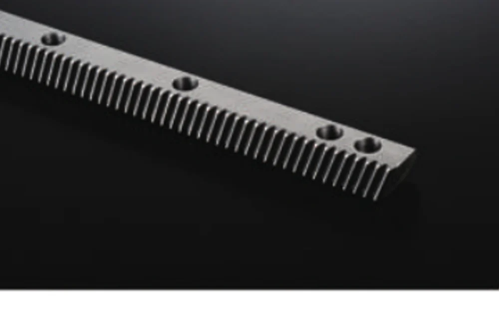
Precision Helical Gear Rack
For smooth long-travel rack drives where helical geometry suits the drive.
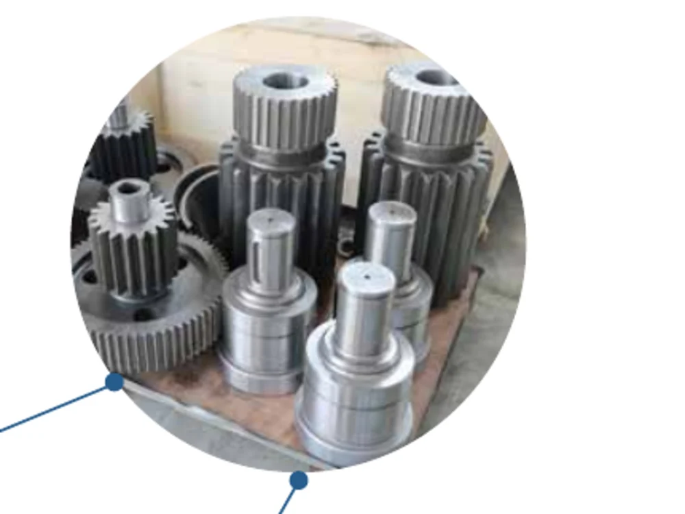
Helical Pinion
Mating pinion with bore, shaft or interface geometry matched to the drive.
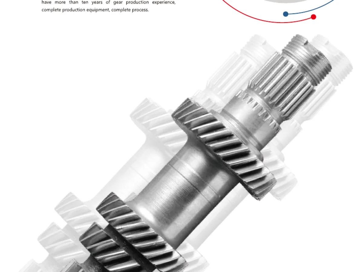
Pinion Shaft
Useful when the gear and output shaft need to be integrated into one component.
Installation details can erase or preserve the value of a precision rack
Support the pinion and gearbox so that robot acceleration does not deflect the mesh out of alignment.
Provide a practical way to set and re-check engagement after installation or maintenance.
Protect the rack from welding debris, grinding dust or floor contamination where the rail crosses active production areas.
Information to send with the application enquiry
Include robot model/mass, maximum payload, rail travel, target speed and acceleration, duty cycle, required repeatability, gearbox output details and the preferred rack mounting arrangement. For dual-drive or master/slave axes, identify how the two sides will be synchronized.
If some values are still open, mark them as design targets. That is more useful than inserting a guessed specification that later becomes difficult to change.
Envie os detalhes que definem a peça.
Um orçamento útil começa com a geometria e o contexto operacional. Envie o desenho, a quantidade e os requisitos de controle; para eixos acionados por cremalheira, adicione o curso, a velocidade, a aceleração, a carga e as informações sobre o pinhão ou a caixa de engrenagens de acoplamento, quando disponíveis.
Como encomendar: A quantidade mínima de encomenda (MOQ) é flexível, variando conforme o tipo de produto e o valor do pedido. Para novos clientes, as amostras podem ser de 1 a 5 unidades; pedidos com modelos variados são aceitos a partir de USD 1.500, enquanto pedidos de 1 a 2 unidades podem ser considerados mediante um preço unitário mais elevado.
Cronograma e condições: As peças padrão têm um prazo de entrega de 10 a 25 dias úteis, os componentes personalizados de 20 a 45 dias e os equipamentos para projetos de 45 a 120 dias. Os termos EXW, FOB, CIF e DAP são comumente utilizados; FCA, CFR, CPT, CIP e DDP podem ser discutidos caso a caso.